CANDE is public-domain computer program developed for the structural design and analysis of buried culverts; hence the acronym CANDE stands for Culvert ANalysis and DEsign. CANDE’s finite-element methodology is based on a two-dimensional slice of the culvert installation so that both the structure and soil mass are modeled as a combined soil-structure system subjected to an incremental loading schedule. Buried culverts of any shape, size and material, including corrugated metal, reinforced concrete and thermoplastic, may be analyzed and designed to withstand dead weight, incremental soil-layer loading, temporary construction loads and surface loads due to vehicular traffic.
A particularly unique feature of CANDE’s output is the automatic evaluation of the structural design in terms of safety measures against all failure modes (design criteria) associated with the structural material. The user has the option to analyze and design the structure using Load Resistance Factor Design (LRFD) or Working Stress (WS) methodologies.
Because of the generality offered by the finite-element solution methodology, CANDE is also applicable to the design and analysis of other soil-structure interaction problems such as underground storage facilities, storm water runoff chambers, retaining walls, tunnel liners, and protective structures. Thus, the words “culvert” or “pipe ” can generally be regarded to represent a general underground structure.
Perhaps the easiest way to understand CANDE’s overall architecture and capabilities is to view it from the perspective of a user who is using CANDE to solve a particular soil-culvert problem. To initiate a CANDE solution, the user begins by making several top-level choices as illustrated in the following flow chart.
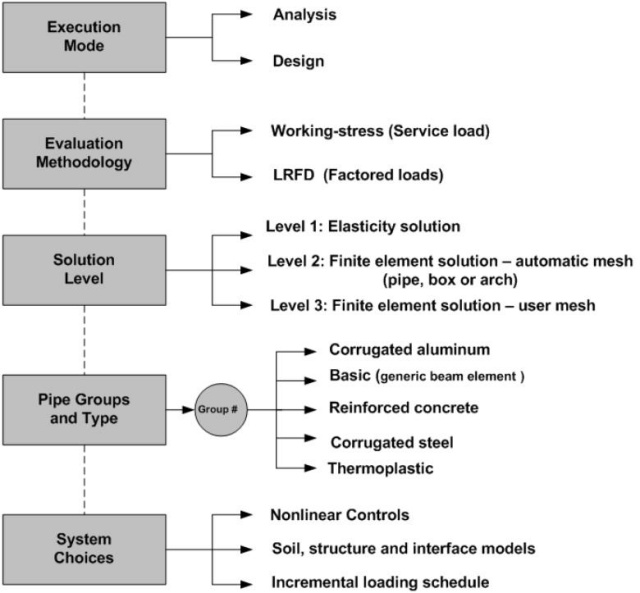
The top-level choices are shown in shaded boxes designated as; Execution Mode, Evaluation Methodology, Solution Level, Pipe Groups and Type, and System Choices. To the right of the shaded boxes are the various choices that may be selected for each top-level category. The particular set of choices for the top-level categories dictates the subsequent stream of input data. It also controls the solution flow path through the program as well as characterizing the nature of the output. Each top-level category is discussed below
Execution Mode is the choice between design and analysis. By analysis it is meant that a particular culvert and soil system are defined in terms of geometry, material properties and loading conditions and solved by the chosen solution level. The solution output provides an evaluation of the culvert in terms of its safety for all potential modes of failure associated with the structural material and shape of the culvert. The evaluation of the culvert’s safety is reported either in terms of safety factors or in ratios of factored demand-to-factored capacity depending on the user’s choice of the Evaluation Methodology. The analysis mode is generally the most useful and commonly used choice for the execution mode.
The alternative execution mode, called design, implies that the culvert shape, materials and loading conditions are defined exactly like the analysis case. However, the culvert’s cross-sectional properties are not defined, but rather, the desired safety factors or the desired LRFD design weights are specified. CANDE achieves a design solution through an iterative series of analysis solutions. That is, an initial trial cross-section is devised by the program and successively modified after each analysis until the design criteria are satisfied in an optimum manner. The design output lists the required cross-sectional properties of the culvert, which, of course, depend on the culvert type. For example, design solutions for corrugated metal culverts are given in the required corrugation size and gage thickness while reinforced concrete is given in the required area of reinforcement steel for one or two cages. Automated design solutions are limited to certain classes of standard soil-culvert systems.
Evaluation Methodology is the choice between a working-stress solution and a LRFD solution. A working-stress solution means the applied loads are the actual (or perceived) set of loads acting on the soil-structure system, referred to as the service-loading schedule. Thus, the service-loading schedule represents the actual dead weight of the structure, the actual weight density of the various soil zones, and the actual pressures and forces from construction equipment and live loads. Evaluation of the culvert’s performance under the working stress option is reported in terms of safety factors for each design criterion associated with the selected culvert type. A safety factor is defined as a ratio of actual capacity-to-actual demand. For example, the safety factor for the design criterion based on thrust stress is the material yield stress divided by the maximum computed thrust stress.
A LRFD solution means the service-loading schedule is increased by individualized load factors. The user begins by defining the service-loading schedule in exactly the same manner as for working-stress methodology. Later in the input stream, the user selects appropriate load factors to be applied to each load step so that the dead loads, earth loads, and live loads may be assigned individual factors as required by AASHTO LRFD specifications. Evaluation of the culvert’s performance under the LRFD option is provided in terms of ratios of factored demand-to-factored capacities for each design criterion associated with the selected culvert type. An evaluation ratio should be less than 1.0 in order for a given design criterion to be considered safe.
Solution Level (1, 2, or 3) provides a choice that corresponds to successively increased levels of analytical sophistication. The solution level concept permits the user to choose a degree of rigor and modeling fidelity commensurate with the details and knowledge of the culvert-soil system under investigation. For example, Level 1 is useful for screening and comparing various circular-shaped culverts in deep burial. Level 2, considered the “work-horse” of CANDE, is applicable to many common culvert shapes including circular, elliptical, box and arch installations, but limited to center-line symmetry for loading and geometry. Level 3 is virtually unlimited in modeling the structure shape, soil system and loading conditions. Level 2 and Level 3 share a common finite element solution methodology and only differ in the manner of input data: automatic versus user defined.
Level 1 is based on the well known Burns and Richard elasticity solution and is suitable for circular culverts deeply buried in homogenous soil subjected to gravity loading. Overall, Level 1 has limited application but is useful as a learning tool on the comparative behavior of different culvert types and soil stiffness.
Level 2 , known as the automatic finite element option, relieves the user from the burden of generating and debugging a finite element mesh, i.e., defining node numbers and coordinates and element connectivity arrays. Rather, Level 2 automatically constructs the finite element mesh based on a few physical input parameters. Level 2 offers three fundamental choices for culvert shape, referred to as pipe-mesh, box-mesh and arch-mesh options. The pipe-mesh option is for round- or elliptical-shaped culverts, the box-mesh option is for rectangular-shaped culverts, and the arch-mesh option is for two- or three-segmented arches including straight leg segments. Each of these “canned mesh shapes” are specialized by a set of physical input parameters such as the culvert dimensions, the installation type (embankment or trench), bedding dimensions, height of cover, and the number of incremental construction layers.
Level 3 brings the full power of the finite element method to solve complicated and/or important soil-structure systems that are outside the scope of Level 2. In this case the finite element mesh topology must be devised and input by the user. CANDE has many helpful techniques to expedite the generation of finite element meshes, however, they require some learning on the part of the user. Whether using Level 2 or Level 3, CANDE offers the user many features that are especially useful for realistically modeling soil-structure problems. Some key features are listed below:
- Incremental construction – the capability to simulate the physical process of placing and compacting soil layers, one lift at a time, below, along side and above the culvert as the installation is constructed.
- Interface elements – the ability to simulate the frictional sliding, separation and re-bonding of two bodies originally in contact. Typically these elements are used between the culvert and soil and between trench soil and in situ soil.
- Soil elements and models – soil elements are high-order continuum elements with a suite of soil models ranging from linear elastic to highly nonlinear. The so-called Duncan and Duncan/Selig soil models are very representative of the nonlinear soil behavior in most culvert installations.
- Large deformation and buckling – an updated Lagrange formulation that has the ability to accurately track culvert deformations up to and beyond its buckling capacity.
- Pipe elements and models – beam-column elements that may be used to model culvert structures and other structures such support braces. Special nonlinear material models are available for corrugated metal, reinforced concrete and thermoplastic.
Pipe Groups and Type is the choice for the number of pipe groups and the pipe type assigned to each group. A single “pipe group” is defined as a connected series of beam-column elements that are identified with only one pipe-type name; aluminum, basic, concrete, plastic, or steel. For example, all the “canned meshes” in Level 2 are composed of a single pipe group whose beam-column elements define the overall structural shape by tracing a continuous path around the culvert’s periphery.
Level 3 provides the user with ability to choose up to 301 pipe groups thereby offering a great deal of modeling power. For example, two groups may be assigned independent node numbers (no nodes in common) so that they represent independent structures. Alternatively, element groups may be arbitrarily joined together at common nodes to model cell-like structures or composite structures such as a corrugated metal arch roof placed on a reinforced concrete U-shaped base. Indeed the multi-group option provides virtually unlimited modeling capabilities to define any configuration within CANDE’s two-dimensional framework.
Each pipe-type name is associated with a corresponding pipe-type subroutine, forming the heart of CANDE's architecture. All pipe-type subroutines perform three main functions:
- Process input data along with stored data to generate initial pipe stiffness.
- Modify pipe element stiffness properties during nonlinear iterations.
- Evaluate the pipe’s design criteria at the end of each converged load step.
In the design mode there is a 4th function, which is to resize the pipe wall properties after each trial design repetition until the design criteria are satisfied. The assumptions behind these four functions are noted for each pipe-type name in the following paragraphs wherein default material properties built in to CANDE relieve the user of defining most input data.
Corrugated aluminum wall properties are characterized by cross-sectional area, moment of inertia and section modulus, which represent the geometry of the corrugation’s waveform per unit length. The aluminum pipe-type subroutine has built-in tables for commercially available corrugation sizes as well as realistic default values for all linear and nonlinear material properties. Aluminum’s material behavior is simulated with a bilinear stress-strain model with an initial elastic response up to yield stress followed a hardening plastic response, identical in tension and compression. All unloading is assumed linear elastic. Design criteria for corrugated aluminum include strength limits for thrust stress against material yielding in hoop compression, global buckling, seam strength rupture and a limit on the amount of plastic penetration through the cross section Finally, a performance limit on the allowable defection, typically taken as 5% of the total rise, completes the set of design criteria.
Reinforced concrete wall sections are defined by the concrete wall thickness with up to two rows of reinforcing steel, typically placed near the inner and outer surface with specified cover depths. In tension, concrete behavior is characterized by cracking when tension stress levels exceed the tensile strain limit. When this occurs the pre-existing tensile stresses are redistributed to the uncracked section, and the cracked location is assumed not to heal for any subsequent tensile loading. In compression, concrete is simulated with a tri-linear stress-strain curve. Initially, the concrete response is linear up to a specified strain level after which the concrete exhibits plastic-hardening behavior. When the compressive stress reaches the ultimate strength limit (fc’), the stress-strain response becomes perfectly plastic with no increase in stress as compressive strain increases. Reinforcing steel behavior is characterized by an elastic-plastic stress-strain model, which becomes perfectly plastic when the steel yield stress is reached in tension or compression. Design criteria for reinforced concrete culverts include strength limits for yielding of steel reinforcement, crushing of concrete in compression, diagonal cracking due to shear failure, and radial cracking due to curved tension steel (also called bowstringing). Finally, a performance limit on the allowable flexure crack width, typically taken as 0.01 inches, completes the set of design criteria. In the CANDE-2015 program two additional concrete pipe types have been added to the pipe-type library; one for rib-shaped cross sections and the other for concrete-filled circular tubes. In both new pipe types, the concrete stress-strain model is capable of simulating the behavior of fiber-reinforced concrete.
Additional reinforced concrete pipe types are; (1) CONRIB for rib-shaped cross sections and/or fiber-reinforced concrete, and CONTUBE for circular cross sections encased in fiberglass tubes.
Thermoplastic pipes have three options to characterize the wall sections; smooth, profile or general. Smooth refers to a uniform wall (gun barrel) whose cross-section properties are completely defined by the wall thickness. Profile refers to the majority of manufactured plastic pipe whose wall section properties may be characterized by the geometry of sub-elements such as web, valley, crest, liner and links. General refers to an arbitrary properties described generically by the wall’s area and moment of inertia per unit length. Material properties are assumed linear elastic with default values provided for high-density polyethylene, polyvinyl chloride and polypropylene for both short-term and long-term loading conditions. A nonlinear local buckling algorithm is provided for the profile option wherein the profile’s section properties are reduced in proportion to the amount of compressive strain computed in the sub elements. Design criteria for thermoplastic pipes include strength limits for thrust stress against material yielding in hoop compression and global buckling. Another strength state is a limit on the maximum outer fiber combined strain (hoop plus bending strain). Performance limit states include allowable vertical deflection and maximum allowable tensile strain, dependent on type of plastic.
Corrugated steel wall properties, like corrugated aluminum, are are characterized by cross-sectional area, moment of inertia and section modulus, which represent the geometry of the corrugation’s waveform per unit length. The steel pipe-type subroutine has built-in tables for commercially available corrugation sizes as well as realistic default values for all linear and nonlinear material properties. Steel’s material behavior is simulated with a bilinear stress-strain model with an initial elastic response up to yield stress followed a hardening plastic response, identical in tension and compression. All unloading is assumed linear elastic. Design criteria for corrugated steel include strength limits for thrust stress against material yielding in hoop compression, global buckling, seam strength rupture and a limit on the amount of plastic penetration through the cross section. Finally, a performance limit on the allowable defection, typically taken as 5% of the total rise, completes the set of design criteria.
Basic pipe-type is not associated with any particular wall geometry or material. Therefore, it is not associated with any design criteria and is only applicable to the analysis execution mode. Further, the basic pipe-type model is limited to linear elastic properties. One unique feature of the basic pipe type is that each individual beam-column element in the ‘basic pipe-type group” may be assigned individual section properties and material properties. Perhaps, the most useful function of the basic pipe type is in Level 3 applications to serve as special structural components in addition to the culvert structures such as struts or temporary bracing
System Choices include a suite of soil models to choose from including the popular hyperbolic forms of Duncan, Duncan and Selig, and Hardin as well as the standard linear forms for isotropic elastic, orthotropic elastic, and overburden dependent models. Predefined model parameters are installed in the program for simulating crushed rock, sands, silts and clays under a range of compaction conditions. The CANDE-2015 programs includres a Mohr-Coulomb elastoplatic model as well as a modfication to the Duncan/Selig model to simulate plastic-like behavior for unloading conditions.
Another system choice is the interface condition between the soil and culvert. The user may select a bonded interface or a friction interface that permits frictional sliding and separation during the loading schedule. Interface elements may also be used between the backfill soil and in situ soil wall for trench installations.
Similar to the interface element, the link element allows the user to connect any two pipe groups with either a pinned connection or a fixed-moment connection. Moreover, the link element is equipped with a death option permitting the user to remove temporary struts, simulate pipe erosion, and/or create voids in the soil mass.
Still another system choice is the option to include large deformation analysis. This is particularly useful for investigating large, flexible culverts under heavy loading. Associated with the large deformation analysis is the capability to predict the global buckling capacity the soil-structure system, which provides a direct factor of safety against collapse.
In summary, this brief writeup is intended to inform the reader whether or not CANDE has the capabilities needed for his or her particular problem. For more technical depth, the reader is referred to the documents in CANDE's download, which include User Manual and Guidelines, Solution Methods and Formulations Manual, and Tutorial of Applications Manual.
CANDE HOME